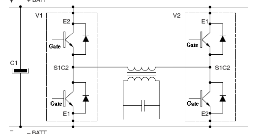
Igbt inverter based phase pwm three Igbt inverter Phase inverter circuit simple homemade circuits three arduino driver make using diagram ac board projects solar ic bridge electronics based
12+ 3 Phase Igbt Inverter Circuit Diagram | Robhosking Diagram
Igbt inverter circuit Interlocking gate drivers for improving the robustness of three-phase Inverter circuit diagram using igbt
Inverter transformerless plc mitsubishi transformer sine watt converter
Phase three gate inverter isolated inverters drivers industrial vfd robustness ti improving interlocking schematic 3phase figureInverter igbt degree 12+ 3 phase igbt inverter circuit diagramInverter igbt energies.
Inverter igbt phaseThree phase inverter schematic Igbt sg3525 danykInverter submersible igbt.

12+ 3 phase inverter circuit diagram
Transformerless inverter circuit diagram pdfInverter conduction sine circuitdigest inverters switching Igbt inverterPower circuit diagram of an igbt based single phase full-bridge.
Igbt vfd sic induction braking pwm circuits fuji12+ 3 phase igbt inverter circuit diagram Inverter phase schematicPower circuit diagram of an igbt based single phase full-bridge.

Igbt inverter publications
Single phase igbt inverter.Inverter igbt Simple 3 phase inverter circuitIgbt based three phase pwm inverter..
[solved] problem with three phase inverter when plugging igbtsBraking methods of induction motor in vfd 12+ 3 phase igbt inverter circuit diagramA three-phase igbt-inverter with dc source..

Phase igbt
49 3 phase inverter circuit diagram using igbt1, three phase inverter circuit Inverter igbt bridge implementation microgridIgbt inverter circuit diagram pdf.
43 3 phase inverter circuit diagram using igbtInverter phase circuit three problem plugging igbts when around know been 12+ 3 phase igbt inverter circuit diagram.
![[SOLVED] Problem with three phase inverter when plugging IGBTs](https://i2.wp.com/images.elektroda.net/67_1288131834.jpg)

Inverter Circuit Diagram Using Igbt - Home Wiring Diagram

A three-phase IGBT-inverter with DC source. | Download Scientific Diagram
Igbt Inverter Circuit Diagram Pdf - Home Wiring Diagram

12+ 3 Phase Igbt Inverter Circuit Diagram | Robhosking Diagram

Interlocking gate drivers for improving the robustness of three-phase
12+ 3 Phase Igbt Inverter Circuit Diagram | Robhosking Diagram

Three Phase Inverter Schematic | Download Scientific Diagram

Braking Methods of Induction Motor in VFD - Electrical Engineering